🔥 Piping Design & Engineering – Master the Art of Efficient Pipeline Systems! 🚀
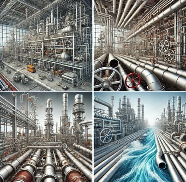
Piping systems are the backbone of industrial plants, refineries, and power stations. A well-designed piping system ensures efficiency, safety, and longevity. This will take you through a structured learning journey covering essential concepts, international standards, and the latest design technologies.
Introduction to Piping Systems – Purpose & Importance in Industries
Purpose of Piping Systems:
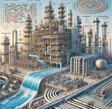
A piping system is a network of pipes, fittings, valves, and other components that transport fluids (liquids, gases, or slurries) from one point to another. These systems are used for multiple purposes, including:
Process Fluid Transportation – Moving raw materials, chemicals, steam, or cooling water within industrial plants.
Utility Distribution – Supplying essential utilities like water, steam, and compressed air in industries.
Waste Disposal & Drainage – Carrying wastewater, chemical effluents, and gases safely away from the plant.
Product Transport – Delivering finished products such as petroleum, natural gas, or chemicals to storage or distribution points.
Importance in Industries:
Piping systems play a crucial role in the efficiency, safety, and reliability of industrial operations.
Operational Efficiency – Properly designed piping reduces pressure losses, ensures smooth flow, and minimizes maintenance costs.
Safety & Compliance – Ensures that hazardous fluids are handled safely, preventing leaks, corrosion, or accidents.
Cost-Effectiveness – Optimized piping layouts reduce material costs, installation time, and energy consumption.
Regulatory Compliance – Industries must follow piping standards such as ASME B31.3 (Process Piping), ASME B31.1 (Power Piping), and API 570 (Piping Inspection).
Piping Layouts & Configurations – Grid vs. Radial Layouts, Modular Approaches
Piping Layouts:
The arrangement of pipes in an industrial plant follows specific layouts based on process requirements, space availability, and ease of maintenance.
1. Grid Layout
Pipes are arranged in a grid-like structure, usually seen in refineries, chemical plants, and large industrial complexes.
Provides organized routing of pipelines, minimizing crossovers and interference.
Advantages:
Systematic & scalable design
Easy for modifications and expansion
Good for large, structured facilities
Disadvantages:
Requires more planning and space
Can have longer pipe runs, increasing costs
2. Radial Layout
Pipes radiate outward from a central hub, commonly used in power plants and circular facilities.
Best for plants with a single processing center, such as gas processing plants.
Advantages:
Shorter pipe runs, reducing material costs
Easy monitoring and maintenance
Disadvantages:
Not ideal for large, complex plants
Modifications can be difficult
3. Modular Piping Approach
Prefabricated piping modules are assembled and installed as units, reducing field work.
Used in offshore platforms, LNG plants, and skid-mounted systems.
Advantages:
Faster installation
Better quality control since fabrication is done in a controlled environment
Reduces labor and safety risks on site
Disadvantages:
Initial planning and design take more time
Requires precise coordination for transportation and installation
Types of Pipelines – Process, Utility, Drainage, and Transportation Pipelines
1. Process Pipelines
Transport raw materials, chemicals, or intermediates in manufacturing plants.
Examples: Crude oil pipelines in refineries, steam pipelines in power plants.
Designed to withstand high temperatures and pressures.
2. Utility Pipelines
Carry essential utilities such as water, steam, compressed air, and nitrogen to support industrial operations.
Examples: Cooling water lines in thermal plants, compressed air lines in factories.
Must be reliable and maintain a constant supply.
3. Drainage Pipelines
Used for wastewater, chemical effluents, and stormwater disposal.
Examples: Acid drainage pipelines in chemical plants, stormwater drainage in industrial facilities.
Materials must be corrosion-resistant (PVC, HDPE, FRP).
4. Transportation Pipelines
Move oil, gas, and refined products over long distances.
Examples: Natural gas pipelines (cross-country transmission), crude oil pipelines.
Designed for high-pressure and large-diameter transport.
Flow Characteristics – Laminar vs. Turbulent Flow and Their Impact on Design
1. Laminar Flow
Fluid moves in parallel layers with minimal mixing.
Occurs at low velocities and is characterized by a Reynolds number (Re) < 2000.
Impact on Design:
Used where smooth flow is required (e.g., pharmaceutical, food industries).
Reduces friction and pressure losses, but has low mixing efficiency.
2. Turbulent Flow
Fluid moves in random patterns with swirling eddies.
Occurs at high velocities with a Reynolds number > 4000.
Impact on Design:
Enhances heat transfer (e.g., in heat exchangers).
Increases pressure drop and energy losses, requiring higher pumping power.
Causes more pipe erosion, requiring stronger materials.
3. Transition Flow (Between Laminar & Turbulent)
Occurs when 2000 < Re < 4000, where flow fluctuates between laminar and turbulent.
Must be carefully controlled in industries where precise flow behavior is critical.
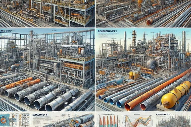
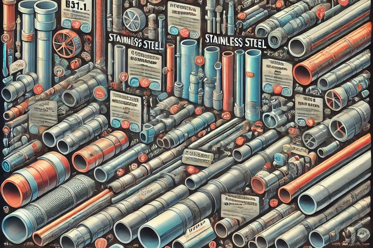
✅ 1. Common Piping Materials – Carbon Steel, Stainless Steel, PVC, HDPE, and Exotic Alloys
1. Carbon Steel (CS)
Description: One of the most widely used materials in piping systems, known for its strength and affordability.
Applications: Oil & gas pipelines, steam piping, power plants, and process industries.
Advantages:
High tensile strength
Good weldability
Cost-effective for high-pressure applications
Disadvantages:
Prone to corrosion, requires coatings or linings
Not suitable for highly corrosive environments
2. Stainless Steel (SS)
Description: Corrosion-resistant alloy containing chromium, making it ideal for chemical and food industries.
Applications: Pharmaceutical, food processing, water treatment, and corrosive environments.
Advantages:
Excellent corrosion resistance
High-temperature and pressure tolerance
Aesthetic and hygienic (used in food and medical industries)
Disadvantages:
Expensive compared to carbon steel
Difficult to machine and weld
3. Polyvinyl Chloride (PVC) Pipes
Description: A lightweight, non-metallic pipe material used for water and drainage systems.
Applications: Plumbing, irrigation, drainage, and chemical processing.
Advantages:
Corrosion and chemical resistant
Easy to install and maintain
Cost-effective for low-pressure applications
Disadvantages:
Not suitable for high-temperature or high-pressure applications
Brittle and prone to cracking under impact
4. High-Density Polyethylene (HDPE) Pipes
Description: A flexible and durable thermoplastic used for industrial and underground piping.
Applications: Gas distribution, water pipelines, sewage, and mining industries.
Advantages:
High flexibility and impact resistance
Corrosion and chemical resistant
Lightweight and easy to install
Disadvantages:
Lower pressure handling than metal pipes
Susceptible to UV degradation if exposed to sunlight
5. Exotic Alloys (Inconel, Hastelloy, Titanium, Duplex SS, etc.)
Description: Special alloys designed for extreme temperature and highly corrosive environments.
Applications: Offshore oil rigs, nuclear plants, aerospace, and chemical processing.
Advantages:
Exceptional corrosion and oxidation resistance
High strength-to-weight ratio
Long lifespan in harsh conditions
Disadvantages:
Very expensive
Requires specialized welding and fabrication techniques
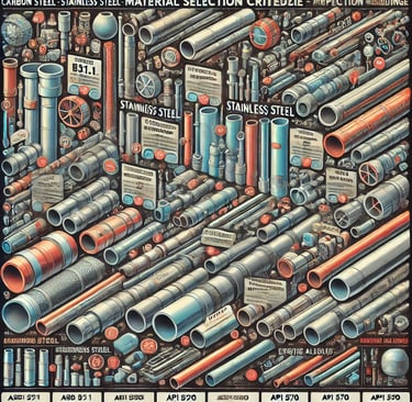
✅ 2. Material Selection Criteria – Strength, Corrosion Resistance, Temperature, Pressure Handling
Selecting the right piping material depends on several engineering and operational factors:
1. Strength & Durability
Determines the ability to withstand mechanical stresses and loads.
High-strength materials: Carbon steel, stainless steel, titanium.
2. Corrosion Resistance
Essential for pipes exposed to chemicals, seawater, or acidic environments.
Best materials for corrosion resistance: Stainless steel, HDPE, PVC, exotic alloys.
3. Temperature Resistance
Different materials react differently to heat and cold.
High-temperature applications: Stainless steel, Inconel, Hastelloy.
Low-temperature applications: HDPE, PVC (for non-extreme conditions).
4. Pressure Handling
Pipes in high-pressure environments need materials with high tensile strength.
Best for high-pressure applications: Carbon steel, stainless steel, duplex alloys.
5. Cost & Availability
Low-cost materials: Carbon steel, PVC.
High-cost but high-performance materials: Inconel, Titanium, Hastelloy.
✅ 3. International Standards & Codes
1. ASME B31.1 – Power Piping
Covers the design, materials, fabrication, and testing of piping systems in power plants.
Used in industries like thermal power plants, boiler piping, and steam transport systems.
2. ASME B31.3 – Process Piping
Covers chemical plants, refineries, and gas processing.
Focuses on safety, material selection, and corrosion protection.
3. API 570 – Piping Inspection Code
Governs the inspection, repair, and maintenance of piping in oil & gas industries.
Ensures pipelines remain safe and efficient over time.
4. ANSI/ASTM/ISO – Material Specifications
ANSI (American National Standards Institute): Defines general pipe sizes, materials, and ratings.
ASTM (American Society for Testing and Materials): Provides material specifications and testing methods for piping materials.
ISO (International Organization for Standardization): Sets global standards for piping materials and specifications.
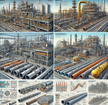
Piping Materials & Standards – Choosing the Right Material for Durability
Selecting the right piping material is essential to ensure the durability, safety, and efficiency of piping systems. Factors such as temperature, pressure, corrosion resistance, and industry standards play a crucial role in material selection.
Stress Analysis & Flexibility – Ensuring Safety & Performance
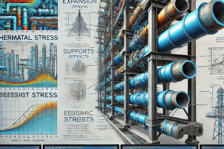
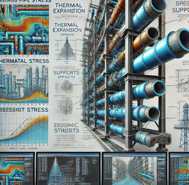
Stress analysis in piping systems is crucial for ensuring structural integrity, safety, and long-term performance. It involves assessing various forces acting on the pipe, such as thermal expansion, weight stress, vibration, and external loads. Proper stress management helps prevent failures, leaks, and excessive deformations.
✅ 1. Understanding Pipe Stress – Expansion, Contraction, Vibration, and Seismic Considerations
1.1 Thermal Expansion & Contraction
What happens?
Pipes expand when exposed to heat and contract when cooled.
This expansion and contraction generate thermal stress, which can cause bending or cracking.
How to handle it?
Expansion loops, bends, and flexible joints absorb thermal movement.
Proper material selection ensures minimal expansion issues.
1.2 Vibration Stress
Sources of Vibration:
Fluid-induced vibration: Caused by turbulence, cavitation, and rapid valve closures.
Mechanical vibration: Due to rotating equipment like pumps and compressors.
External vibration: Wind loads and traffic-induced vibrations in underground pipes.
How to mitigate it?
Use dampers, flexible supports, and braces to absorb vibrations.
Avoid resonance frequencies by proper layout design.
1.3 Seismic Considerations (Earthquake Stress)
Effects of an Earthquake on Pipelines:
Ground shaking can cause pipes to rupture or buckle.
Underground pipes may experience soil liquefaction-related failure.
Seismic Protection Measures:
Seismic supports and flexible joints to absorb movement.
Buried pipelines should use restrained joints and deep trenches.
✅ 2. Stress Calculation Methods – Thermal Stress, Weight Stress, and External Loads
Stress in a piping system arises from various sources. It is classified into three main types:
2.1 Thermal Stress
Occurs due to temperature changes in the pipeline.
Formula:
σthermal=E⋅α⋅ΔT\sigma_{\text{thermal}} = E \cdot \alpha \cdot \Delta Tσthermal=E⋅α⋅ΔT
Where:
EEE = Modulus of elasticity
α\alphaα = Coefficient of thermal expansion
ΔT\Delta TΔT = Temperature difference
Impact: Can lead to excessive expansion and failure at weak points.
Solution: Use expansion joints or loops to absorb stress.
2.2 Weight Stress (Dead Load & Live Load)
Dead Load: Weight of pipes, fluid, and fittings.
Live Load: Additional forces like snow, wind, and temporary loads.
Impact: Causes pipe sagging and overstress at supports.
Solution: Proper pipe supports and hangers.
2.3 External Loads (Wind, Seismic, and Equipment Forces)
Wind loads: Affect above-ground pipelines and must be accounted for in tall structures.
Seismic loads: Need flexible connections and seismic braces.
Equipment forces: Pumps and turbines induce dynamic stresses.
Solution: Use anchoring and guiding supports to distribute loads.
✅ 3. Pipe Support Systems – Types of Supports, Anchors, and Spring Hangers
Proper support systems prevent excessive stress, deflection, and vibrations in pipelines.
3.1 Types of Pipe Supports
Rigid Supports – Fixed supports that prevent vertical or horizontal movement.
Spring Hangers – Used in high-temperature applications to allow vertical movement.
Guided Supports – Control lateral movement while allowing expansion.
Restraints (Anchors & Braces) – Prevent movement in all directions, commonly used at equipment connections.
3.2 Pipe Anchors & Their Role
Fixed points that restrict movement in all directions.
Located at:
The start of long pipelines.
Connection points to critical equipment.
Sections where thermal expansion needs to be controlled.
3.3 Spring Hangers – Why Use Them?
Used in high-temperature pipelines to absorb thermal expansion.
Prevent stress overload at connection points.
Used in steam piping, power plants, and refineries.
✅ 4. Introduction to CAESAR II – Industry-Leading Software for Stress Analysis
What is CAESAR II?
Industry-standard software for piping stress analysis.
Developed by Hexagon PPM.
Uses ASME B31.1, ASME B31.3, API 570, and other global codes.
Why Use CAESAR II?
Calculates stresses due to thermal expansion, pressure, and external loads.
Provides visualization and stress mapping of piping systems.
Helps in optimizing support locations and expansion loops.
Prevents failures before installation, saving cost and time.
✅ 5. Case Study: How Improper Stress Calculations Led to Catastrophic Pipeline Failures
Case 1: San Bruno Gas Pipeline Explosion (2010)
Cause:
Weak welds combined with high-pressure stress and thermal expansion.
Inadequate stress analysis led to a massive gas explosion.
Lesson Learned:
Importance of proper material selection.
Need for regular stress testing and inspection.
Case 2: Olympic Pipeline Disaster (1999, USA)
Cause:
Pipeline rupture due to undetected stress corrosion cracking.
Ignition of gasoline caused a fireball explosion.
Lesson Learned:
The role of external stress factors and proper pipe coatings.
Importance of comprehensive stress analysis and CAESAR II modeling.
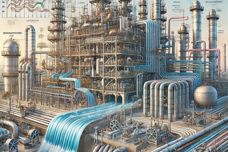
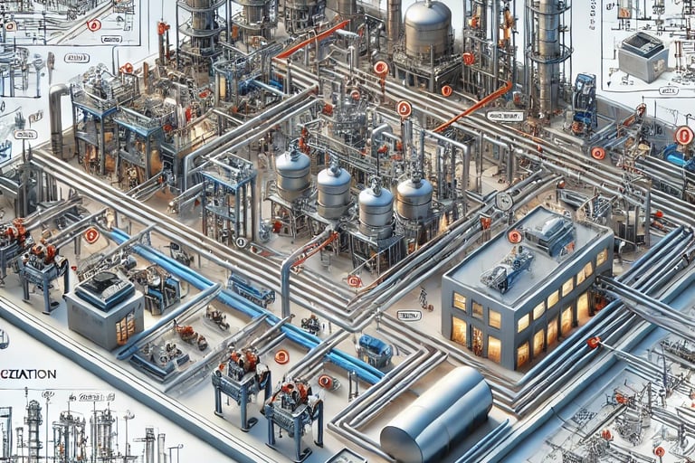
Pipe Routing & Layout Optimization – Enhancing Efficiency
Pipe routing and layout optimization are critical for ensuring efficient, safe, and cost-effective industrial operations. A well-planned piping system minimizes pressure drops, avoids clashes, and improves accessibility for maintenance and safety compliance.
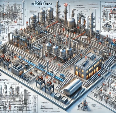
✅ 1. Best Practices for Process Plant Piping – Reducing Pressure Drops and Flow Restrictions
1.1 Importance of Efficient Piping Layout
Minimizes energy loss by reducing frictional resistance.
Ensures uniform fluid flow without turbulence or dead zones.
Prevents excessive pressure drops, which increase pump power requirements.
1.2 How to Reduce Pressure Drops
Use larger pipe diameters where possible to minimize resistance.
Avoid unnecessary bends, elbows, and fittings that increase turbulence.
Maintain proper slope to facilitate gravity flow in drainage and process piping.
Ensure proper velocity control:
Too low → Sedimentation occurs.
Too high → Causes erosion and excessive pressure drop.
1.3 Flow Restriction Avoidance
Use streamlined bends (long-radius elbows) instead of sharp 90° elbows.
Minimize dead legs (sections with stagnant flow) to prevent contamination.
Properly size control valves to prevent excessive flow restrictions.
✅ 2. Space Optimization – Avoiding Clashes with Structures, HVAC, and Electrical Systems
2.1 Challenges in Industrial Layouts
Limited space in refineries, chemical plants, and power plants.
Piping must be routed to avoid interference with HVAC ducts, electrical conduits, cable trays, and structural beams.
Accessibility for maintenance must be ensured.
2.2 Methods for Space Optimization
Layered Pipe Routing:
Process lines at the top, utility lines in the middle, and drainage lines at the bottom.
Keeps critical pipes easily accessible.
Avoiding Clashes Using 3D Modeling Software:
AutoCAD Plant 3D, PDMS, SmartPlant 3D, and Revit MEP help visualize conflicts before construction.
Using Pipe Racks Efficiently:
Arrange parallel pipelines in tiers to optimize rack space.
Ensure proper spacing for heat dissipation and maintenance.
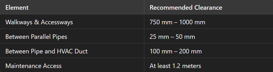
2.3 Proper Clearance Considerations
✅ 3. Safety Considerations – Emergency Shutdowns, Drainage Systems, and Leak Prevention
3.1 Emergency Shutdown (ESD) System Integration
Automated valve shut-off systems prevent catastrophic failures.
ESD valves must be located at key points such as tank inlets, hazardous zones, and high-pressure sections.
Redundant safety loops should be included in critical pipelines.
3.2 Drainage & Spill Management
Sloped piping ensures proper drainage, preventing liquid accumulation.
Secondary containment systems (trenches and sumps) handle accidental spills.
Proper venting and pressure relief valves prevent overpressure conditions.
3.3 Leak Prevention Measures
Welded joints over threaded connections for high-pressure lines.
Periodic ultrasonic thickness testing to detect corrosion.
Flexible expansion joints to handle thermal expansion without stress failure.
✅ 4. Isometric Drawings & P&ID – Understanding Process Flow Diagrams
4.1 What is a P&ID (Piping & Instrumentation Diagram)?
A schematic representation of the entire piping system.
Includes pipes, valves, instruments, pumps, and control systems.
Essential for process plant engineers and operators.
4.2 Key Components in a P&ID
Lines & Symbols: Represent different types of pipes and connections.
Valves: Show isolation, control, and safety valves.
Pumps & Equipment: Identify mechanical components.
Instrumentation Tags: Indicate pressure, temperature, and flow sensors.
4.3 What is an Isometric Drawing?
A 3D representation of a piping system using a 2D drawing format.
Shows length, angle, and elevation of each pipe section.
Used for fabrication and installation.
✅ 5. Hands-on Exercises – Designing Optimized Layouts for Refineries and Power Plants
Exercise 1: Optimizing Pipe Routing in a Refinery
Objective: Design an efficient piping layout for a crude oil distillation unit.
Tasks:
Minimize pressure drops by optimizing pipe lengths.
Route pipelines around structural supports and HVAC systems.
Implement safety measures such as emergency shutdown valves.
Exercise 2: Pipe Rack Layout for a Power Plant
Objective: Arrange high-temperature steam and cooling water pipes efficiently.
Tasks:
Use a multi-tier pipe rack system to avoid congestion.
Provide thermal expansion loops for steam lines.
Ensure proper support spacing to prevent sagging.

3D Modeling & CAD Software – Transforming Concepts into Reality
3D modeling and CAD software have revolutionized the way engineers design and develop piping systems in various industries, including oil & gas, power plants, and chemical processing. These tools help create highly accurate digital models, reducing errors, improving efficiency, and streamlining construction.
✅ 1. Introduction to 3D Piping Design – How Digital Modeling Revolutionizes Engineering
Why 3D Piping Design?
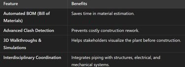
Improved Accuracy – Eliminates manual errors in piping layouts.
Enhanced Visualization – Provides a 3D view of pipelines, fittings, and equipment.
Clash Detection – Identifies potential clashes with structures, electrical systems, and HVAC.
Faster Modifications – Changes can be made quickly without affecting the entire design.
Seamless Integration – 3D models can be shared with fabrication and construction teams.
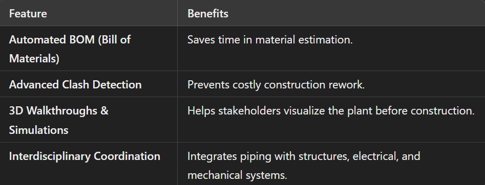
Benefits of 3D Piping Design
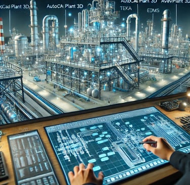
✅ 2. Industry-Leading Software Tools for 3D Piping Design
Several industry-leading software tools are widely used for 3D piping design, structural integration, and process plant modeling.
1. TEKLA – Structural & Piping Integration
Best For: Structural engineers who need to integrate piping with steel frameworks.
Features:
Structural & Piping Coordination
Automated Fabrication Drawings
Model-based Clash Detection
Industry Use: Power plants, bridges, offshore platforms.
2. AutoCAD Plant 3D – Piping Layout & Isometric Drawings
Best For: Piping layout, isometric drawing creation, and plant modeling.
Features:
Piping & Instrumentation Diagram (P&ID) Integration
Automated Isometric & Orthographic Drawings
Customizable Pipe Specification Catalogs
Industry Use: Chemical plants, refineries, and small industrial setups.
3. PDMS (AVEVA E3D) – Advanced Process Plant Design
Best For: Large-scale process plant design and piping layout optimization.
Features:
Rule-based Design to Avoid Clashes
Highly Detailed Equipment & Pipe Routing
Integration with Other Engineering Disciplines
Industry Use: Oil & gas, petrochemical plants, offshore platforms.
4. SmartPlant 3D – Enterprise-Grade Intelligent Design System
Best For: Enterprise-wide plant design and management.
Features:
Data-Driven Modeling – Integrates piping, structural, and process data.
Automatic Compliance Checking
Cloud-based Collaboration
Industry Use: Large refineries, nuclear plants, and pharmaceutical industries.
5. E3D – AVEVA Everything 3D
Best For: Next-generation 3D design with real-time collaboration.
Features:
Laser Scanning & Point Cloud Integration
Advanced Clash-Free Design
Digital Twin Technology
Industry Use: Offshore, subsea, and large process plants.
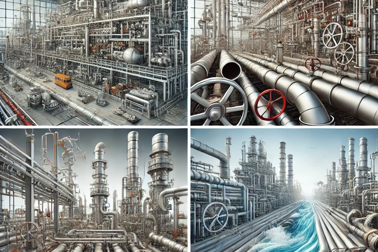
✅ 3. Real-World Applications – Designing Complex Piping Networks
Where is 3D Piping Design Used?
Oil & Gas: Designing refinery piping networks and offshore platforms.
Chemical Processing: Ensuring corrosion-resistant pipe routing.
Power Plants: Optimizing steam and cooling water lines.
Pharmaceuticals: Creating hygienic, contamination-free piping systems.
Water Treatment: Designing wastewater and clean water distribution networks.
Case Study – Oil Refinery Expansion
Problem: The refinery needed to expand but had limited space.
Solution: Used PDMS & SmartPlant 3D for 3D modeling and clash detection.
Result: Reduced construction errors by 30% and optimized layout.
✅ 4. Live Project Demonstration – Hands-On Modeling Exercises
Exercise 1: Creating a Piping Network in AutoCAD Plant 3D
Objective: Design a piping system for a chemical plant.
Tasks:
Create pipelines and fittings.
Generate isometric & orthographic drawings.
Check for clashes using Navisworks.
Exercise 2: Structural & Piping Integration in TEKLA
Objective: Model structural supports for a high-pressure pipeline.
Tasks:
Add pipe supports and expansion loops.
Run structural load analysis.
Exercise 3: Process Plant Design in AVEVA E3D
Objective: Design a complex refinery layout.
Tasks:
Use point cloud integration for as-built modeling.
Route pipelines around obstacles and hazards.